Blade Designs
Due to the constraints of manufacturing and test facilities available for this research, propellers were designed to operate in the incompressible region with a maximum Mach number of 0.3 at a Reynolds number of approximately 100,000.
The propellers studied in this research are two blade propellers with a diameter of 155mm. The reference propeller is a straight blade Graupner 5.9”x 5.9” CAM speed propeller, which is able to fly at a cruise velocity of 27 m/s at 12,100 RPM. Since all propellers were made to mimic the performance of this reference propeller, all designed blades, straight and swept, have the same chord and thickness values at identical radii as the Graupner blade.
There are three types of sweep configurations, which are discussed in detail in the Design Tool section. At this point, the current research is focused on the direct forward sweep design, the study of other configurations is in progress.
Design Tool
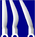
A computer program was developed in order to make the design process more flexible and less time consuming. The program is capable of instantly generating the coordinates of propeller blades with different design configurations. The design options include the operating conditions (RPM, cruise velocity, angle of attack), with a user specified leading edge geometry (figure 1) and airfoil alignment type (figure 2)
Figure 1: Pro/E propeller geometry
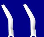
Figure 2: Airfoil alignments of
Translate (left) and Transform (right)
Leading edge geometry includes straight, direct sweep, delayed sweep, and combined sweep. The direct sweep configuration was constructed by extending the leading edge from rroot with a constant sweep angle y until it intersects rtip (figure 3). The delayed sweep configuration was constructed by leaning the leading edge in the direction of rotation at a distance x away from rroot (figure 4). The combined sweep configuration was constructed by joining the backward and forward leaning edges with a tangent arc (figure 5).
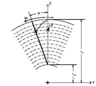
Figure 3: Direct forward swept design configuration
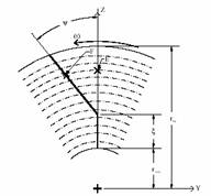
Figure 4: Delayed forward sweep design configuration
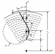
Figure 5: Combined backward-forward swept design configuration
In this research, the main focus is on the direct forward sweep option. The rest of the geometries will be explored aiming to locate the optimal sweep angle for each configuration, and also the overall optimal combination of sweep angle and design.
Airfoil alignment types include transfer, translate and transform. In transfer, the airfoil at each section is aligned parallel to the horizontal line; there is no rotation on the airfoil. In other words, all blades with this alignment type were designed so that the airfoils are exactly the same at identical radial locations. This would ensure that the difference in performance was due solely to the sweep effect. In transform (figure 6), the airfoil at each section is rotated and aligned with the local flow direction. In translate (figure 7), the airfoil is rotated and aligned normal to the leading ledge. The current research is using the transfer option, where airfoil is aligned parallel to the horizontal line. The other two options will be explored and their causes and effects on the performances of the propellers will be studied.
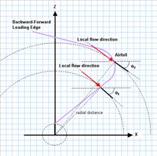
Figure 6: Airfoil Alignment, Transform
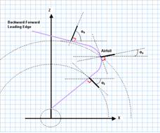
Figure 7: Airfoil Alignment, Translate
Altogether, over 200 configurations are available through this program. In the final report, more design features will be added to the program, such as the scaling options for the blade, different airfoil selections, and add a graphical user interface. If all of these proposed editions are completed, the program would be capable of generating over 700 unique configurations, which would streamline the propeller design process. Blade Designer generates a coordinate file for input to Pro/Engineer where 3D models are obtained, these models are then used for CFD mesh generations.